Double sided pcb board prototype FR4 TG140 impedance controlled PCB
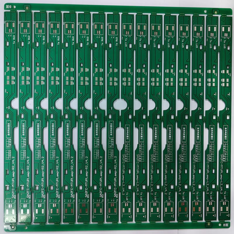
Product Specification:
| Base Material: | FR4 TG140 |
| PCB Thickness: | 1.6+/-10%mm |
| Layer Count: | 2L |
| Copper Thickness: | 1/1 oz |
| Surface treatment: | HASL-LF |
| Solder mask: | Glossy green |
| Silkscreen: | White |
| Special process : | Standard |
Application
Circuit boards with controlled impedance have the following characteristics:
1. Strictly control the manufacturing process of the circuit board, including material selection, printed wiring, layer spacing, etc., to ensure the impedance stability of the circuit;
2. Use specific PCB design tools to ensure that the impedance meets the design requirements;
3. In the entire PCB layout and routing, use the shortest path and reduce bending to ensure the stability of impedance;
4. Minimize the crossover between the signal line and the power line and the ground line, and reduce the crosstalk and interference of the signal line;
5. Use matching impedance technology on the high-speed signal transmission line to ensure the purity and stability of the signal;
6. Use interlayer connection technology to reduce coupling noise and electromagnetic radiation;
7. According to different impedance requirements, select the appropriate layer thickness, line width, line spacing and dielectric constant;
8. Use a specific test instrument to perform an impedance test on the circuit board to ensure that the impedance parameters meet the design requirements.
Why can conventional impedance control only be a 10% deviation?
Many friends really hope that the impedance can be controlled to 5%, and I have even heard of the 2.5% impedance requirement. In fact, the impedance control routine is 10% deviation, a little more strict, can achieve 8%, there are many reasons:
1, the deviation of the plate material itself
2. Etching deviation during PCB processing
3. The iation of flow rate caused by lamination during PCB processing
4. At high speed, the surface roughage of copper foil, PP glass fiber effect, and DF frequency variation effect of media must understand the impedance.
Where are circuit boards with impedance requirements generally used?
Circuit boards with impedance requirements are usually used for high-speed signal transmission, such as high-speed digital signal transmission, radio frequency signal transmission and millimeter wave signal transmission. This is because the impedance of the circuit board is related to the transmission speed and stability of the signal. If the impedance design is unreasonable, it will affect the transmission quality of the signal and even cause signal loss. Therefore, in occasions that require high signal transmission quality, it is usually necessary to use circuit boards with impedance requirements.
FAQs
Impedance measures the opposition of an electric circuit when alternating current is applied to it. It is the combination of the capacitance and the induction of an electric circuit at high frequency. Impedance is measured in Ohms, similarly to resistance.
A few factors that affect impedance control during PCB design include trace width, copper thickness, dielectric thickness and dielectric constant.
1)The Er is inversely proportional to the impedance value
2)The dielectric thickness is proportional to the impedance value
3)The line width is inversely proportional to the impedance value
4)The copper thickness is inversely proportional to the impedance value
5)The lines spacing is proportional to the impedance value(differential impedance)
6)The solder resistance thickness is inversely proportional to the impedance value
In high frequency applications matching the impedance of PCB traces is important in maintaining data integrity and signal clarity. If the impedance of the PCB trace connecting two components does not match the components' characteristic impedance, there may be increased switching times within the device or the circuit.
Single ended impedance, Differential impedance, Coplanar impedance and Broadside Coupled Stripline
Products categories
-

Electric car prototype printed circuit board ma...
-
Industrial PCB electronics PCB high TG170 12 la...
-

halogen-free copper clad printed circuit board ...
-

Printed circuit board for vehicle led light fas...
-

Halogen-free Automotive circuit board quick tur...
-
Printed circuit boards lighting for BYD Electri...